Smooth Jazz plays, the clickedy clack of an old typewriter is heard a shadowy black and white figure sits at a desk as their cigar puffs gentle rise and caress the ceiling.
“It was Easter” the page reads. “I can’t say this was an easy find but after the months of searching we cracked the case. We found the device.”
Alright enough of that crap….
So @maythegoat and I went to a charity shop and found an old Japanese brand Nakajima AX-150 electronic typewriter. Of course the only sensible option next was to hack about with it.
The RRP new is around £200, we got it second hand for £10. It was in fantastic nik and worked perfectly so hey bit of a steal. Charity shops tend to be a gold mind of cheap stuff to hack about with.

The next step was research, unfortunately there isn’t a whole lot of data available online so we took to the next best thing. Tearing it apart.
After carefully mangling up the ribbon in the ink cartridge (cough may cough) we had a good look at the print mechanism and the main circuit board.
After some googling around the electric typewriter scene (yes that’s a thing) I figure its probably mid to late 80’s in design although our one was likely manufactured early 90’s. Despite that the system doesn’t seem too complicated; so we figure out what we can, fail to look up IC chip reference numbers on the internet, and resort to decided what we’re going to do to it….
After some deliberation and diagramming of ideas we reckon we’ll start by making a printer. With this sort of machine we have three options of where to intercept the signal, Top level at the keyboard out, at the processing chip and send out own signals to process, or very low level at the machine level sending out own commands to the actual mechanical hardware.
We decided for the print version to hijack the keyboard out signal.

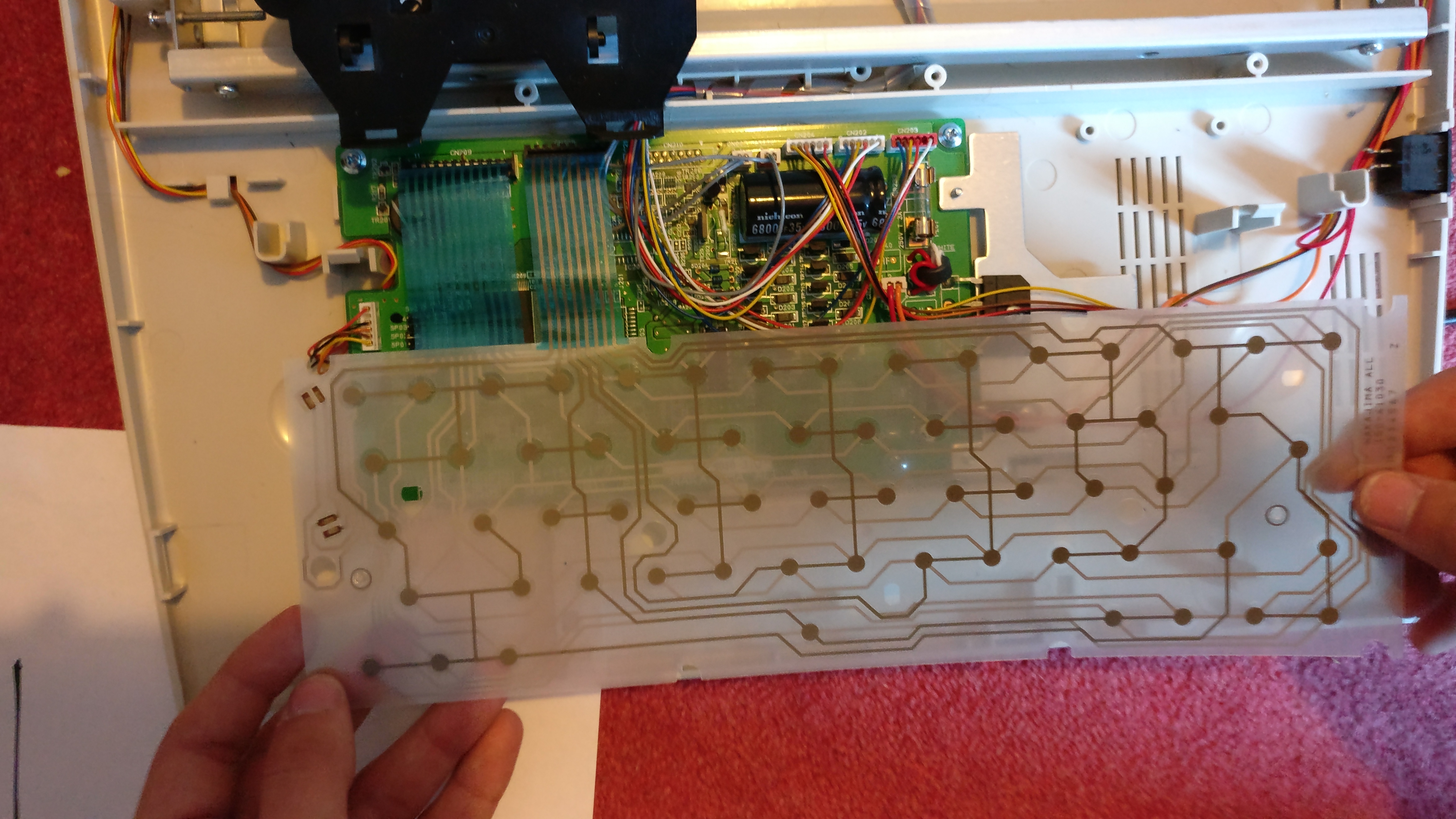
They keyboard mechanism is a simple push pad operation. A spring comes down from the key pressing two contacts together. If you look at the image above you can see two ribbon cables a wider one on the left and a thinner one on the right. We figure it likely uses an ASCII system to transmit characters as the left right has 8 tracks for the 8 bits in one byte of ASCII. This suggests it’s the output wire so the left one bust me the power in cable. So why does the input cable on the left has 11 tracks over 8. Well two are for the two indicator LED’s one for power and one for caps lock. If you’re anything like me and aren’t familiar with keyboard circuitry you’re probably wondering what the other wire is for. Now I could just tell you but to understand properly let me explain it.

This diagram demonstrates how a key press is registered with this keyboard system. What you need to understand is that it essentially completes a circuit and sends power off down several different ‘lanes’ to build the ASCII signal. That circuit however must have power flowing through it the whole time in one way or another not just when a key is pressed else the LED’s wouldn’t work. So the third wire is a negative output or ground wire. It helps to think about the system as the left in being the positive and the right out being the negative. the LED’s are connected to the positive in and the negative out. But remember,the 8 wires should only light up when an ASCII character is to be transmitted. So in order to not have an always on bit in our output we simply have an extra wire in the in ribbon that is actually just a dud output wire. No data is taken from it.
So we’re at a stage where we deiced our plan. Write an arduino program that will convert a string or RTF into ASCII signals and output them synchronously via the GPIO pins. We can then connect these to the out ribbon cable on the circuit board in the typewriter.
After taking it apart and reverse engineering it we put it back together and, much to our relief, it still worked. Unfortunately the ink tape had gotten tangled. So after about an hour of fiddling with cutting it and gluing the tape back to the reel we got it back and running again.
BONUS VIDEOS of it working and being very satisfying…
|
|
Join us next time when we’ll be trying to make it print and most likely swearing a lot. That’s all for now. Taa Raa!
P.S All the images in this are taken from May’s Instagram HERE because I’m an idiot and didn’t take any.
Will next time tho….
promise luv Colon xx

Hello!
Would to chat! I have a pair of Nakajimas nee Swintec State side, and one has a parallel port in, the other doesn’t.
I got my hands on tables for the binary, hex and decimal values for ASCII, “USA Standard,” and control codes if interested, and if you have them, maybe you may be able to help me understand them as I have used the rather pedestrian route of using the IEEE 1284 to USB from monoprice, which isn’t very satisfying.